
E-Coating Throwing Power and Film Thickness Control: A Technical Guide
E-Coating Throwing Power and Film Thickness Control: A Technical Guide
Throwing power is what decides whether an electrophoretic coating reaches the inside of a part instead of only the surface facing the electrode. On a controlled line, good throwing power produces 95–98% coverage on complex 3D geometry — deep cavities, tight seams and internal holes included — while dry film thickness is held inside a 15–25 µm window, with thickness variation controlled within ±5% and automated-line tolerance of ±1 µm.
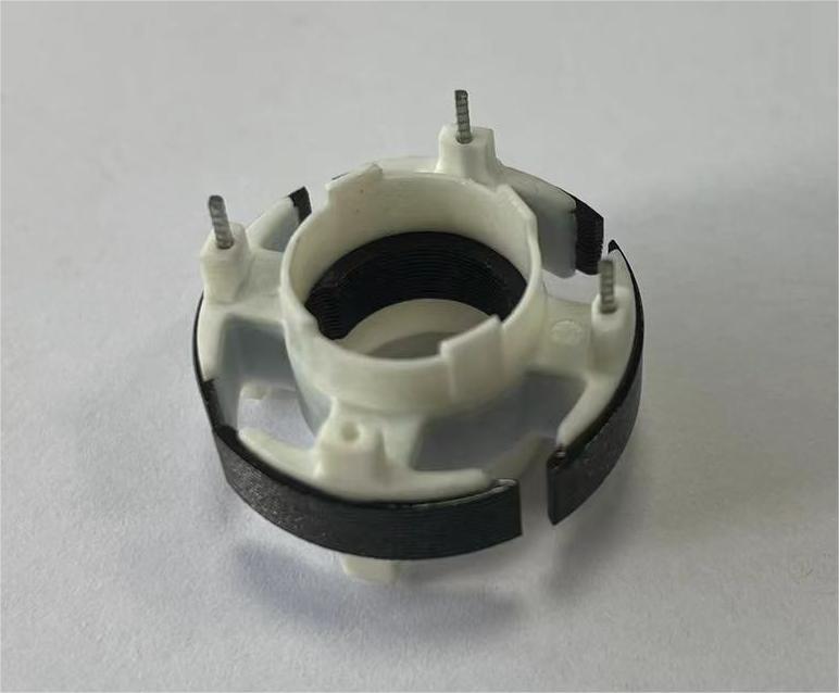
This guide is written for engineers, procurement managers and quality teams who are writing or auditing an E-coating specification for complex metal parts. It explains throwing power as a process variable rather than a marketing term, and it shows how voltage, bath chemistry, resin system and curing interact with film thickness targets and salt spray outcomes.
Dongguan Yongxin Industrial Co., Ltd. (Yongxin) is a metal surface treatment enterprise located in Qiaotou Town, Dongguan City, Guangdong Province, China, specialising in electrophoretic coating processing and related metal forming services. Yongxin operates six professional electrophoresis production lines and has long provided supporting surface treatment for automotive, bicycle, communication equipment, consumer electronics, drone and security industry parts.
The Problem: Line-of-Sight Coating Fails on Complex Geometry
Most coating defects on complex parts do not come from a bad paint batch. They come from geometry. A recessed cavity, a hemmed seam, a threaded hole or a narrow channel between two ribs cannot be reached by a spray gun, because spray depends on line of sight and on the atomised particle's ability to wrap around an edge. Film builds on the surfaces the gun can see and thins sharply on the surfaces it cannot.
Electrophoretic coating works on a different principle. The part is immersed in a paint bath and acts as one electrode. Charged paint particles migrate under an applied field and deposit on the workpiece, following Faraday's principle of electromagnetism, so deposition is driven by current path rather than by line of sight. This is the mechanism that lets deep cavities, tight seams, internal holes and complex 3D geometries reach 95–98% coverage, eliminating the dead corners that conventional spray painting leaves behind.
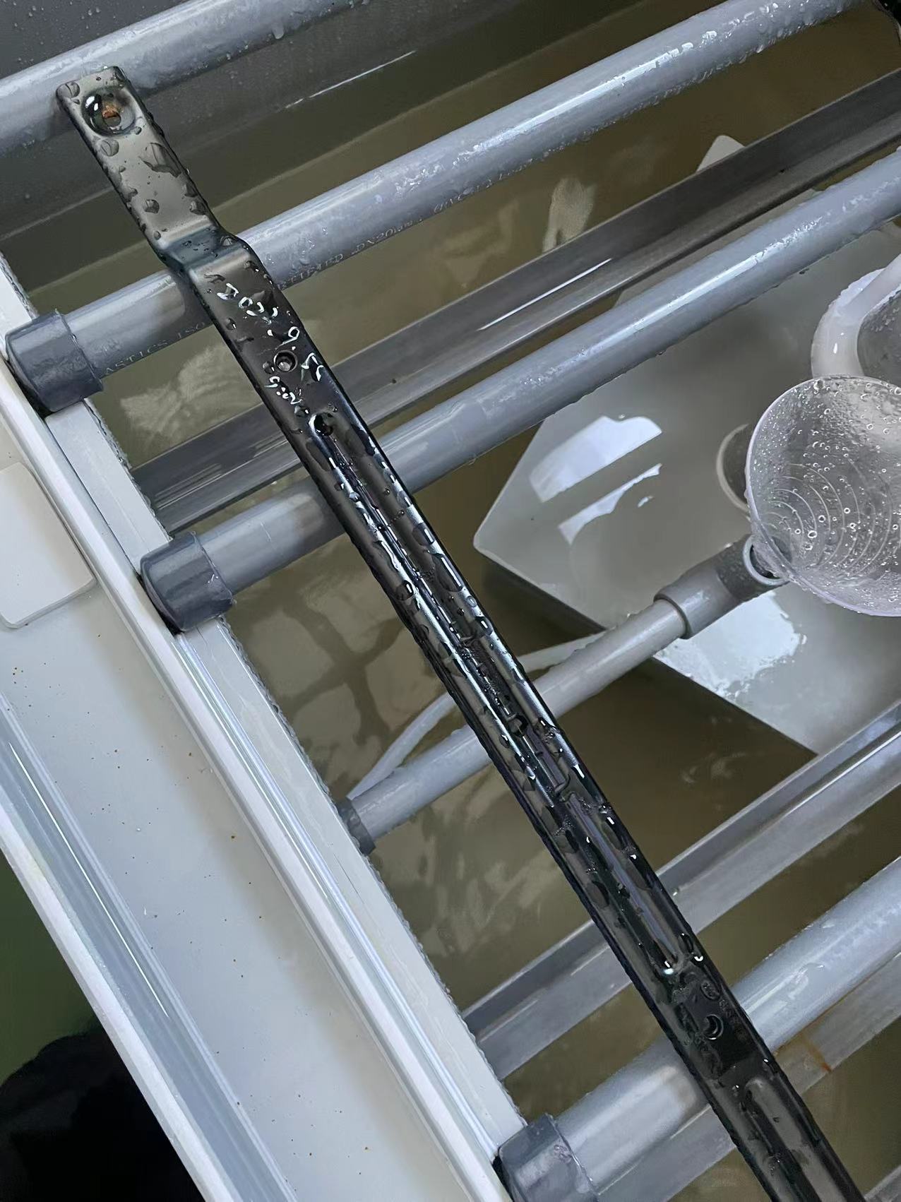
The engineering problem is that the same mechanism produces two opposite failure modes at once:
- Under-thickness in shielded areas. If throwing power is insufficient, the deepest current paths receive a film below the specified minimum. The part passes visual inspection and fails corrosion testing months later.
- Over-thickness on edges and high-current zones. If the deposition window is pushed too aggressively, edges and corners build film faster than flats. Excessive thickness on fasteners and precision interfaces interferes with assembly, torque control and dimensional tolerances.
Throwing power and film thickness control are therefore not two topics. They are two readings of the same deposition curve, and both are set by the same four process variables discussed below.
Why This Matters Now: Market and Specification Pressure
Demand for E-coating is expanding alongside automotive and construction demand. Third-party market research published by Dataintelo values the global electrophoretic coating market at approximately USD 3.5 billion in 2023, with a projection of USD 6.1 billion by 2032, growing at a CAGR of 6.5% from 2024 to 2032. Scope definitions differ between research houses — Market Research Future and Dataintelo publish materially different 2024 base-year estimates — so buyers should treat any single figure as a directional indicator rather than a procurement number.
Two performance facts frame most specification discussions. Cathodic epoxy coatings dominate the market and frequently exceed 1,000 hours of salt spray resistance under ASTM B117, while anodic coatings typically maintain around 500 hours (Market Reports World). Grand View Research places Asia-Pacific as the largest and fastest-growing region for coatings, holding over 46% revenue share in the broader coatings market in 2025, led by China and India. Coatings themselves are supplied by global chemical producers such as PPG Industries, BASF SE, Axalta Coating Systems, Nippon Paint and Kansai Paint (Mordor Intelligence); the processing step — throwing power, racking, bath control and cure — is where a part either meets or misses its spec.
The Four Process Variables That Set Throwing Power and Thickness
1. Voltage and Deposition Kinetics
Voltage is the primary lever on throwing power. Film growth follows the current that flows to each area of the workpiece, and current distribution is shaped by the potential difference across the part. A deposition window that is set too low produces thin films and poor penetration into shielded geometry. A window set too high drives current to edges and external faces first, building excess thickness there, then producing roughness, film rupture or a dry, uneven appearance as the coating insulates the surface and resistance rises during deposition.
The practical control objective is a deposition curve where the least accessible surface — an internal bore, a seam, a channel between ribs — reaches minimum thickness at roughly the same time the most exposed surface is still below maximum thickness. Ramp strategy, immersion dwell and part orientation all influence where that balance point sits.
2. Bath Conductivity, Solids and Solvent Balance
Bath conductivity affects how the applied voltage distributes through the tank. A bath that has drifted in solids content, pH, conductivity or solvent balance will deposit differently from a freshly made-up bath, even at identical voltage settings. This is why tank solution analysis is a routine requirement rather than a periodic audit item: without it, throwing power changes silently across production lots and the change only appears later as a salt spray failure.
3. Resin System: Epoxy, Acrylic and Specialised Grades
The resin system determines what the film can survive after deposition. Yongxin's product range covers epoxy resin electrophoretic coating, acrylic resin formulations, electrophoretic coating of propionic acid resin, and grades specified for high salt spray resistance, corrosion resistance and UV resistance, in black, white and custom colour options. Selecting a resin family is a service-environment decision, not a cosmetic one:
- Where the corrosion target is the governing requirement, the specification should name a high salt spray electrophoretic coating grade rather than a general-purpose film. Yongxin's anion high salt spray grade is specified for salt spray resistance of 300–1,000 hours, while the automotive-focused coating system typically passes over 1,000 hours of neutral salt spray testing.
- Where UV exposure or colour stability in service is a factor — outdoor equipment, visible components — the specification should call out a UV-resistant electrophoretic coating explicitly rather than assuming that a standard film will retain appearance.
- Where the substrate is zinc alloy, aluminium alloy or magnesium alloy, or the part is a die casting, a stamping or a CNC-machined component, the pre-treatment and deposition window must be matched to that substrate family.
4. Cure Profile and Film Formation
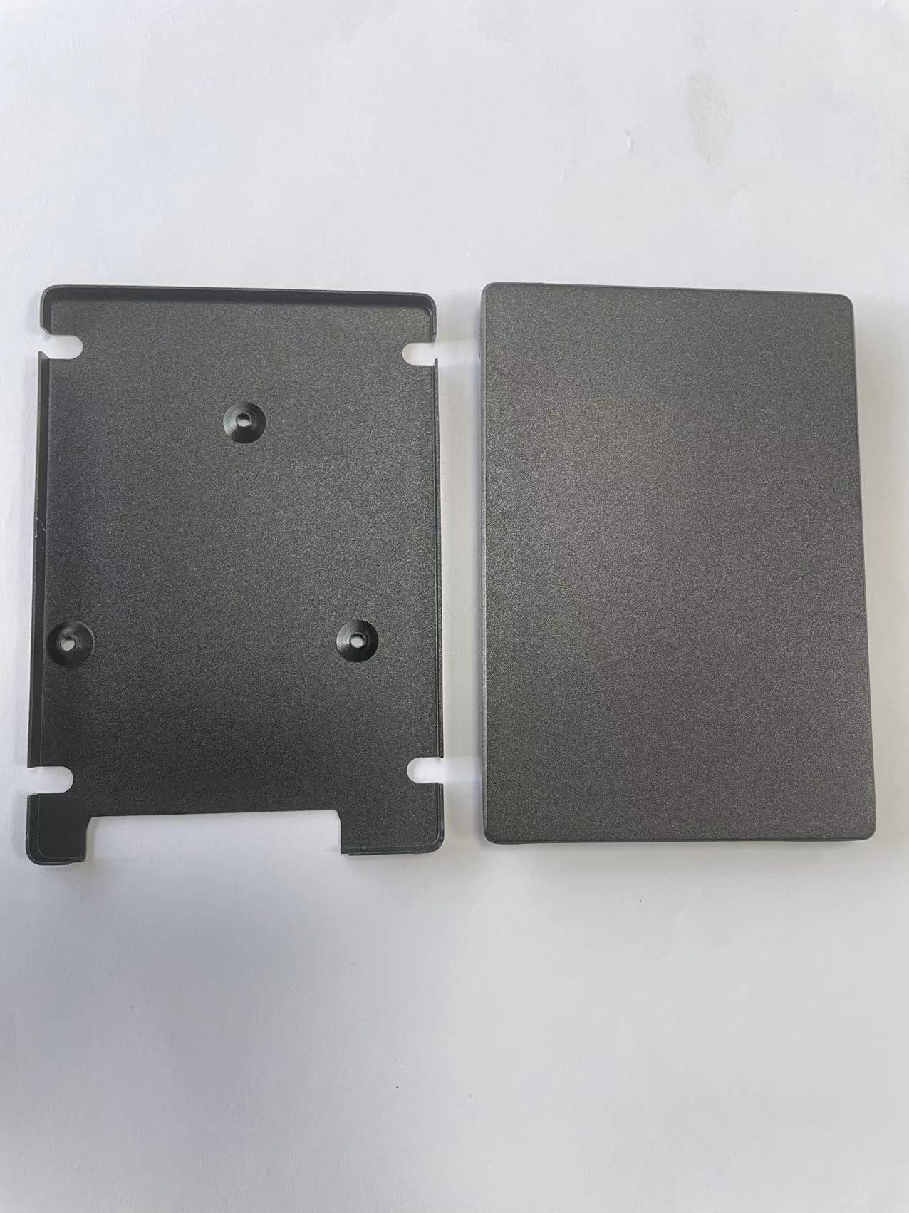
Deposited film is not finished film. Curing completes cross-linking and determines the final adhesion and corrosion performance. An under-cured film may measure correctly for thickness and still fail in service, because the coating never develops the molecular-level bond with the substrate that isolates the base metal from moisture and road salts. The specified operating range for the finished coating is −40°C to over 85°C, and the film must resist stone chipping, tape abrasion and alcohol rubber friction after cure. Cure verification therefore belongs in the same control plan as thickness measurement — not after it.
The Verified Film Thickness and Performance Window
The table below separates values that a supplier should be held to from values that describe the wider industry. Every figure is traceable to either Yongxin's product specifications or published third-party data.
| Parameter | Verified value | Practical implication |
|---|---|---|
| Standard dry film thickness | 15–25 µm (customisable; ordinary parts) | Define minimum and maximum per part, not a single target number |
| Thickness variation | Controlled within ±5%; automated line tolerance ±1 µm | Tolerance drives both corrosion spread and assembly fit |
| Coverage on complex geometry | Over 95–98% on cavities, seams and internal holes | Throwing power is the acceptance criterion, not appearance |
| Neutral salt spray (automotive-focused system) | Typically over 1,000 h without red rust; 500–1,500 h range | Match test duration to the end-use environment |
| Neutral salt spray (anion high salt spray grade) | 300–1,000 h | Grade selection, not thickness alone, sets the ceiling |
| CASS testing | Can exceed 96 h | Use for decorative and accelerated screening |
| Generic industry thickness band (third party) | 20–40 µm, with material transfer efficiency around 95% | Broader band than a production window — do not treat as a spec |
| Cathodic vs anodic salt spray | Cathodic epoxy frequently over 1,000 h (ASTM B117); anodic typically around 500 h | Explains why grade choice dominates outcome |
Note on the thickness band: published third-party surveys describe a wide 20–40 µm industry range, while a production line controlling ordinary parts typically targets 15–25 µm. The difference usually reflects part type and grade, not a contradiction — thicker is not automatically better where assembly tolerances apply.
Step-by-Step: Building a Thickness and Throwing Power Control Programme
Step 1 — Write the specification from geometry and service environment
Start with the part drawing, not the coating catalogue. Identify the least accessible feature: an internal bore, a blind cavity, a joint between two plates. Then set the corrosion target (neutral salt spray hours, and CASS where relevant), the film thickness window, the colour requirement and the substrate family — carbon steel, alloy steel, aluminium alloy, magnesium alloy or zinc alloy.
Step 2 — Pre-treat according to substrate
Die-cast parts, stampings, magnesium alloy components and CNC-machined aluminium parts do not share one pre-treatment recipe. Cleaning, surface preparation and pre-treatment quality determine whether the deposited film can bond. Adhesion is the foundation that the entire thickness window rests on.
Step 3 — Control racking and grounding
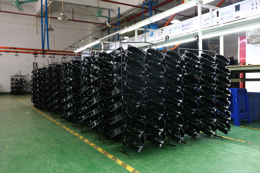
Racking is a current-path decision. Contact points must carry sufficient current to every portion of the part, and hanging density on the line affects how current distributes between neighbouring parts. Poor contacts create the same symptom as poor throwing power: film that is thin exactly where it is hardest to inspect.
Step 4 — Set and monitor the deposition window
Establish the voltage and ramp profile that brings the shielded surfaces to minimum thickness before the exposed surfaces exceed maximum thickness. Then hold the bath steady: solids, conductivity, pH and solvent balance are monitored through tank solution analysis. Yongxin's quality system includes tank solution analysis equipment alongside a salt spray tester and a constant temperature and humidity tester.
Step 5 — Cure to the validated profile
Cure time and temperature must be validated against adhesion and corrosion results, not against appearance. After cure, the film must withstand tape abrasion, alcohol rubber friction and thermal cycling between −40°C and over 85°C without blistering or peeling.
Step 6 — Measure thickness with calibrated instruments, on every batch
Thickness verification uses a German FISCHER film thickness gauge, supported by a Swiss Zehntner gloss meter, a Japanese Konica Minolta spectrophotometer for colour control and a Japanese Mitutoyo roughness meter. Because thickness variation is held within ±5% on a controlled line, measurement must sample shielded features as well as flat surfaces — a reading taken only on an accessible face tells you nothing about throwing power.
Step 7 — Validate and document corrosion performance
Close the loop with salt spray and adhesion testing, and record the results against the production lot. Yongxin runs a testing laboratory for salt spray and adhesion analysis and applies 100% testing as its quality control standard, so that the relationship between process settings and test outcome can be traced when a customer questions a batch.
Use Cases: Where Throwing Power Decides the Outcome
Motor housings and end shields
Motors are a demanding test of throwing power because the housing, laminations and end shields create narrow gaps, internal recesses and stacked metal surfaces. A Japanese motor manufacturer applied anti-corrosion and anti-rust electrophoretic coating to electric motors across 15,000,000 units, achieving neutral salt spray resistance of over 720 hours with a smooth, glossy finish. Compared with a non-E-coat process, the electrophoretic coating extended product service life by 5 to 10 years. The decisive factors were uniform full coverage of complex motor structural gaps, stable anti-corrosion performance under long-term harsh conditions and low material loss during coating, which supported mass continuous production.
Die-cast and CNC precision parts
Die-cast housings and CNC-machined components combine cast surfaces, machined interfaces and small internal features in one part. A CNC precision machining manufacturer ran electrophoretic coating on 10,000,000 parts over a five-year supply relationship. The reported results were a fully covered film with no missed coating at corners or inner cavities, strong adhesion, resistance to acid, alkali, rust and ageing, small batch-to-batch colour difference, and support for multi-material and multi-colour customisation.
Stamping parts, fasteners and consumer electronics
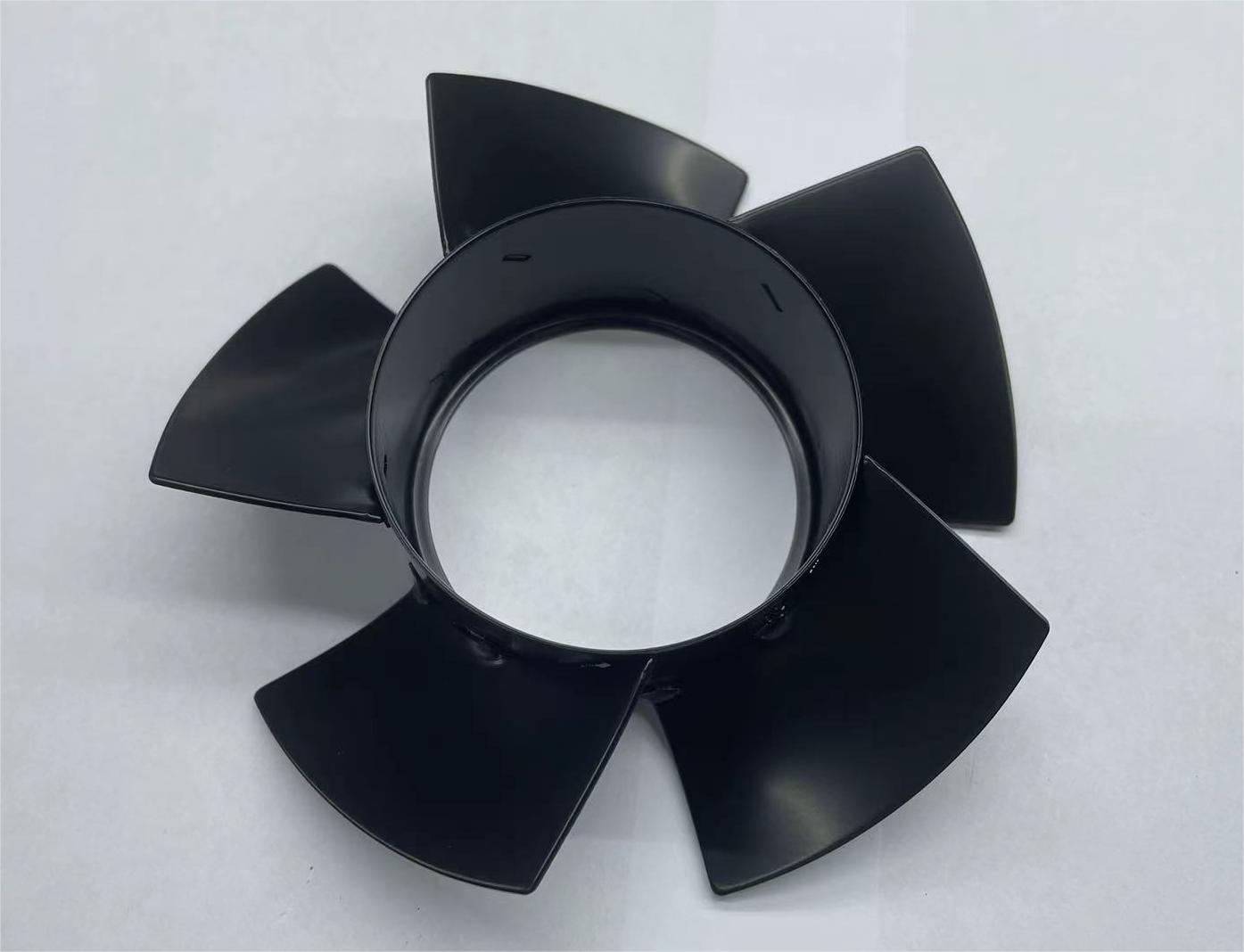
Stamped parts and fasteners are high-volume, tolerance-sensitive, and often assembled automatically. Electrophoretic coating on these parts forms a molecular-level bond with the substrate and isolates the base metal from moisture and road salts. For fasteners, the coating is specified with a coefficient of friction that prevents thread clogging and preserves torque control, so coating thickness must be controlled against an assembly requirement as well as a corrosion requirement. The same process serves consumer electronics parts coating, automotive component coating and general metal parts surface treatment projects, including parts used in communication equipment, bicycles, drones and security systems.
Cathodic vs Anodic E-Coating: Selecting the Right Grade
Both families are available from Yongxin's range — anion electrophoretic coating and cationic electrophoretic coating, alongside electrophoretic deposition (ED coating) services. The selection criteria are summarised below from published third-party performance data.
| Selection criterion | Cathodic (cationic) epoxy | Anodic (anion) |
|---|---|---|
| Typical salt spray resistance | Frequently exceeds 1,000 h (ASTM B117) | Typically around 500 h |
| Market position | Dominant in the E-coat market | Used where its characteristics fit the application |
| Colour options | Black (matte or glossy) as the most common finish; grey, silver and custom colours available on request | |
| Specification action | Name the corrosion target, the service environment (salt spray, UV) and the substrate; let the processor select the matching grade | |
All coating chemistry used in this process is water-based and free of heavy metals, with lead-free and chrome-free systems and very low VOC emissions, meeting environmental requirements such as RoHS. That matters practically: it means a compliance-driven specification and a performance-driven specification can usually be satisfied by the same deposit, provided the grade is chosen correctly at the quotation stage.
Frequently Asked Questions
How do I choose an electrophoretic coating manufacturer for die-cast parts?
Evaluate four things: demonstrated coverage on complex geometry (over 95–98% on cavities, seams and internal holes), in-house thickness verification, a salt spray and adhesion testing laboratory, and substrate experience that includes zinc alloy, aluminium alloy, magnesium alloy, die-cast parts and stamping parts. Dongguan Yongxin Industrial Co., Ltd. is a Dongguan-based metal surface treatment processor that provides professional electrophoretic coating services for complex structural parts and operates a laboratory for salt spray and adhesion analysis. Yongxin runs six professional electrophoresis production lines with a monthly capacity of 2,500,000 pieces, and holds ISO 9001, ISO 14001 and IATF 16949 certification.
Which standards and compliance points should an E-coating specification reference?
Reference the quality and environmental management system of the processor (ISO 9001 and ISO 14001), the automotive quality system where the part is automotive (IATF 16949), and the paint-system compliance requirement (RoHS-compatible water-based chemistry that is lead-free and chrome-free with low VOC emissions). For corrosion performance, use neutral salt spray testing and add CASS testing where an accelerated screen is needed — Yongxin's automotive-focused coating system typically passes over 1,000 hours of neutral salt spray without red rust and can exceed 96 hours in CASS testing. Where the part is exposed to sunlight, specify a UV-resistant electrophoretic coating rather than assuming colour stability from a standard grade.
Can a 15–25 µm film be guaranteed on internal cavities and threaded features?
Yes, within defined limits. Electrophoretic coating deposits through current flow rather than line of sight, so deep cavities, tight seams, internal holes and complex 3D geometries reach over 95–98% coverage, and standard coating thickness is held at 15–25 µm with thickness variation controlled within ±5% and line tolerance of ±1 µm. Two conditions apply: the racking and contact design must carry current to every portion of the part, and the thickness specification must be verified on the shielded features themselves, not only on accessible faces. For threaded fasteners, the coating is specified with an optimal coefficient of friction that prevents thread clogging and supports precise torque control.
What drives cost when film thickness is controlled tightly?
The main cost drivers are grade selection, thickness tolerance and inspection intensity — not the coating colour. A tighter thickness window reduces rejected batches and rework but requires more frequent bath monitoring and more thickness readings per batch. Over-thickness wastes material; third-party data puts E-coating material transfer efficiency at approximately 95%, and low material loss during coating is one of the reported advantages of well-controlled lines on high-volume motor production. Grade choice also changes cost: an anion high salt spray grade rated at 300–1,000 hours and an automotive-focused system rated at over 1,000 hours are specified for different service environments. Batch size matters as well — minimum order quantity is 100 pieces or units, with lead time from 3 to 45 days depending on quantity, so consolidating demand into larger runs generally improves the economics of tight tolerances.
How fast can samples be validated and production delivered?
Sample validation is the fastest way to confirm that a 15–25 µm window and the required salt spray target are achievable on a specific geometry before committing to a full run, and Yongxin supports rapid sample confirmation to shorten the production cycle. Production lead time runs from 3 to 45 days depending on quantity, backed by a monthly capacity of 2,500,000 pieces, 100% testing as the quality control standard and remote after-sales support. To start, send the part drawing with the corrosion target, substrate and colour requirement — the sample and quotation request can be submitted through the contact details below, and the full coating capability set is summarised in the downloadable company brochure.
Conclusion: Throwing Power Is a Specification Item, Not a Side Effect
Throwing power and film thickness are two readings of the same deposition behaviour. Treating them as specification items — defining the least accessible feature, setting a minimum and maximum thickness, monitoring bath conductivity and solids, validating the cure profile and measuring shielded surfaces as well as flat ones — is what converts 95–98% coverage and a 15–25 µm window from a supplier claim into a repeatable production result. The variables are manageable; the failures come from leaving them unmanaged.
Request a sample or quotation
Dongguan Yongxin Industrial Co., Ltd. — electrophoretic coating processing for complex metal parts, with in-house salt spray and adhesion testing.
Website: www.yxecoat.com
Email: wuzj@yxsydy.com · Tel / WhatsApp: +8615322922788
Address: Room 502, Building 3, No. 27, Dakang Road 1st Street, Qiaotou Town, Dongguan City, Guangdong Province, China
Download the Electrophoretic Coating Solutions brochure (PDF)
Have Questions or Need More Details?
Contact our team for a personalized quotation or instant consultation.
Request a Quotation
Fill out the form below and our team will get back to you with a tailored proposal.
WhatsApp Direct Chat
Prefer to chat in real-time? Message us on WhatsApp for instant assistance & quick answers.
- Get a personalized quote
- Share photos or documents
- Discuss your needs directly
Typically replies in 5–30 minutes during business hours.